

Sometimes it’s just not worth it making stuff yourselves, but it’s just better to ‘buy and modify’.
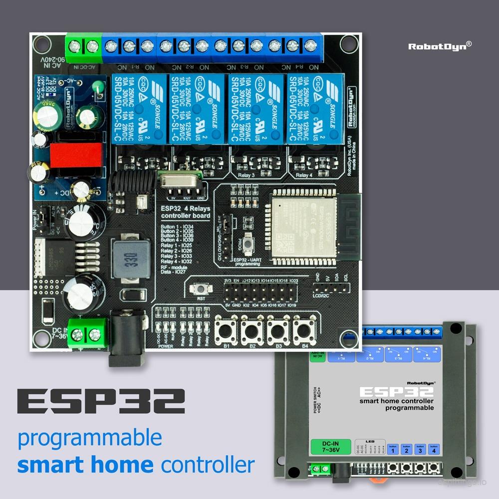
On Aliexpress we found this ESP32R4 Smart Home Controller from a company called RobotDyn that comes with Tasmota preinstalled. It’s got 4 relays (10 Amp), 4 buttons, 7 status LED’s (1 per relay, 1 DC power LED, 1 AC power LED and 1 ESP32 status LED), a 7-36v DC input and a 90-240v AC input. The ‘icing on the cake’ is a 433Mhz receiver/transmitter.
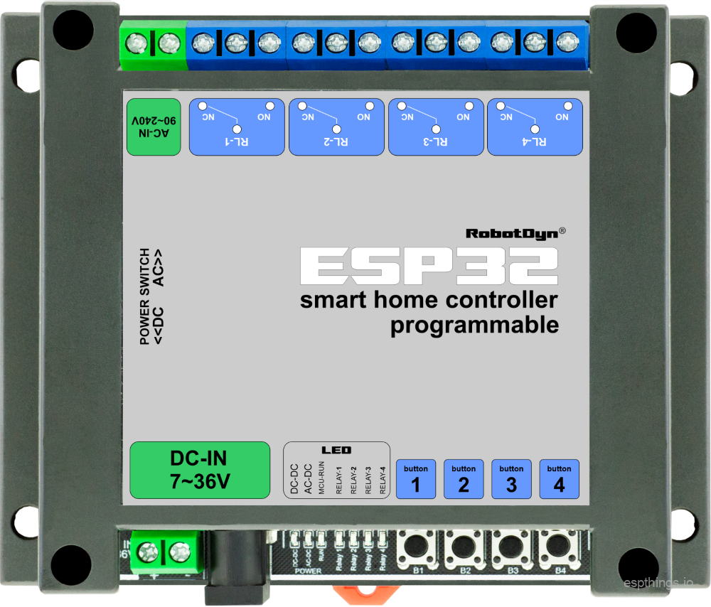
You can buy this for $12 to $15 with or without an enclosure, so this is really a no-brainer.
As we prefer to run esphome firmware, we reflashed the device with a basic OTA esphome config. You can simply do this but connecting a USB TTL(get the red one, CP2102 5PIN) and connect the 3.3v, GND, TX and RX. Please temporarily remove the jumper and DO NOT connect a power supply and USB power at the same time!
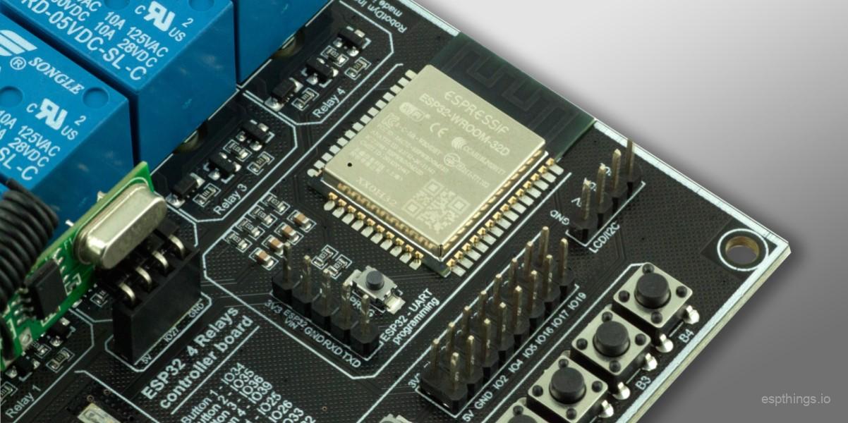
After that we started playing around with the GPIO’s 😉
This is the config we came up with. Everything works great and RAW 433Mhz data is showing up in the logs. Finally a device that just works without a fuzz!
substitutions:
  devicename: esp32-shc-01
  long_devicename: ESP32 Smart Home Controller

esphome:
  name: $devicename
  comment: $long_devicename
  platform: ESP32
  board: esp32doit-devkit-v1

wifi:
  ssid: !secret esphome_wifi_ssid
  password: !secret esphome_wifi_password
  ap:
    ssid: "$devicename Fallback Hotspot"
    password: !secret esphome_ap_password
    ap_timeout: 15s

captive_portal:

web_server:
  port: 80

logger:
  level: DEBUG

api:
  password: !secret esphome_api_password

ota:
  password: !secret esphome_ota_password

sensor:
  - platform: wifi_signal
    name: "$devicename WiFi Signal"
    update_interval: 60s

remote_receiver:
  pin: GPIO27
  dump: rc_switch
  # Settings to optimize recognition of RF devices
  tolerance: 50%
  filter: 250us
  idle: 4ms
  buffer_size: 2kb

switch:
  - platform: gpio
    name: "$long_devicename Relay 1"
    pin: GPIO25
    id: relay1
  - platform: gpio
    name: "$long_devicename Relay 2"
    pin: GPIO26
    id: relay2
  - platform: gpio
    name: "$long_devicename Relay 3"
    pin: GPIO33
    id: relay3
  - platform: gpio
    name: "$long_devicename Relay 4"
    pin: GPIO32
    id: relay4

binary_sensor:
  - platform: gpio
    pin:
      number: GPIO34
      mode: INPUT_PULLUP
      inverted: True
    name: "$long_devicename Button 1"
    on_press:
      then:
        - switch.toggle: relay1
  - platform: gpio
    pin:
      number: GPIO35
      mode: INPUT_PULLUP
      inverted: True
    name: "$long_devicename Button 2"
    on_press:
      then:
        - switch.toggle: relay2
  - platform: gpio
    pin:
      number: GPIO36
      mode: INPUT_PULLUP
      inverted: True
    name: "$long_devicename Button 3"
    on_press:
      then:
        - switch.toggle: relay3
  - platform: gpio
    pin:
      number: GPIO39
      mode: INPUT_PULLUP
      inverted: True
    name: "$long_devicename Button 4"
    on_press:
      then:
        - switch.toggle: relay4
Please be so kind to let us know if this helped you in any way, below in the comments!
Please subscribe to our newsletter!
Great article, simple and concise, just the right information and tips. And the ESPHome configuration file for the RobotDyn ESP32R4v2 board works like a charm, too. Thanks a lot!
Hi Michel, I gave an issue uploading the firmware via serial. Can you please let me know the baud rate.
Also tried to load a HomeAssist generated BIN file via the ESP32R4 gui, but that has failed too.
Any ideas would be greatly accepted.
Cheers,
Mike.
Did you press and hold the ‘program’ button when booting the ESP32R4?
I use the method as described in this video: https://www.youtube.com/watch?v=yMhC6Or0oTY&t=260s
Hi Michel,
I resolved it by simply getting a YP-05 usb to serial board. (my bad, as my home made level shifted circuit didn’t do it. Probably because of the long lead length with high data rates!)
1. Important to remove jumper next to ESP32.
2. Provide 3.3v power to Vin.
3. Hold Prog button while booting – press RST button whilst still holding Prog button – release RST button – then finally release Prog button.
4. ESPHome works a treat uploading FW.
Arduino INO sketch uploading is a bit problematic. Speed of 921600 seems most reliable.
I found that ESPHome complains when saying the switch ports are Pulled Up. It says those GPIO’s [34,35,36,39] don’t support it. And so they aren’t working for me yet.
The relays work a treat.
Did you figure out a way to use the 34-39 pins? So far no luck on my end
Just remove the “mode: INPUT_PULLUP” line for those pins, they’re always in that mode.
Michel, coul you detail how have you achieved to program de ESP32R4 ? What board id in Arduino Ide ? How is the YP05 connected ? Sorry, but I cannot achieve that Ide recognizes the USB port….
Hello
I have one of these and I am trying to access both the buttons and the RF controller with home assistant with MQTT my device has the Tasmota firmware on.
What about Bluetooth function?
Is’t esp32-WROOM, so it’s supported.
Is it possible to power it with 24VAC? I need to use it to replace my conventional thermostat which is currently powered by 24VAC.
No, only DC.